with 2 tube, 1km")
ADSS optical fiber Cable ADSS 12 core PE Span 100 Single Mode (Single Sheath) with 2 tube, 1km
SKU G652D
347 588 FCFA
On Sale
était 347 800 FCFA Save 0%
In stock
1
ADSS optical fiber Cable ADSS 12 core PE Span 100 Single Mode (Single Sheath) with 2 tube, 1km
Product Details
Marque: ZION

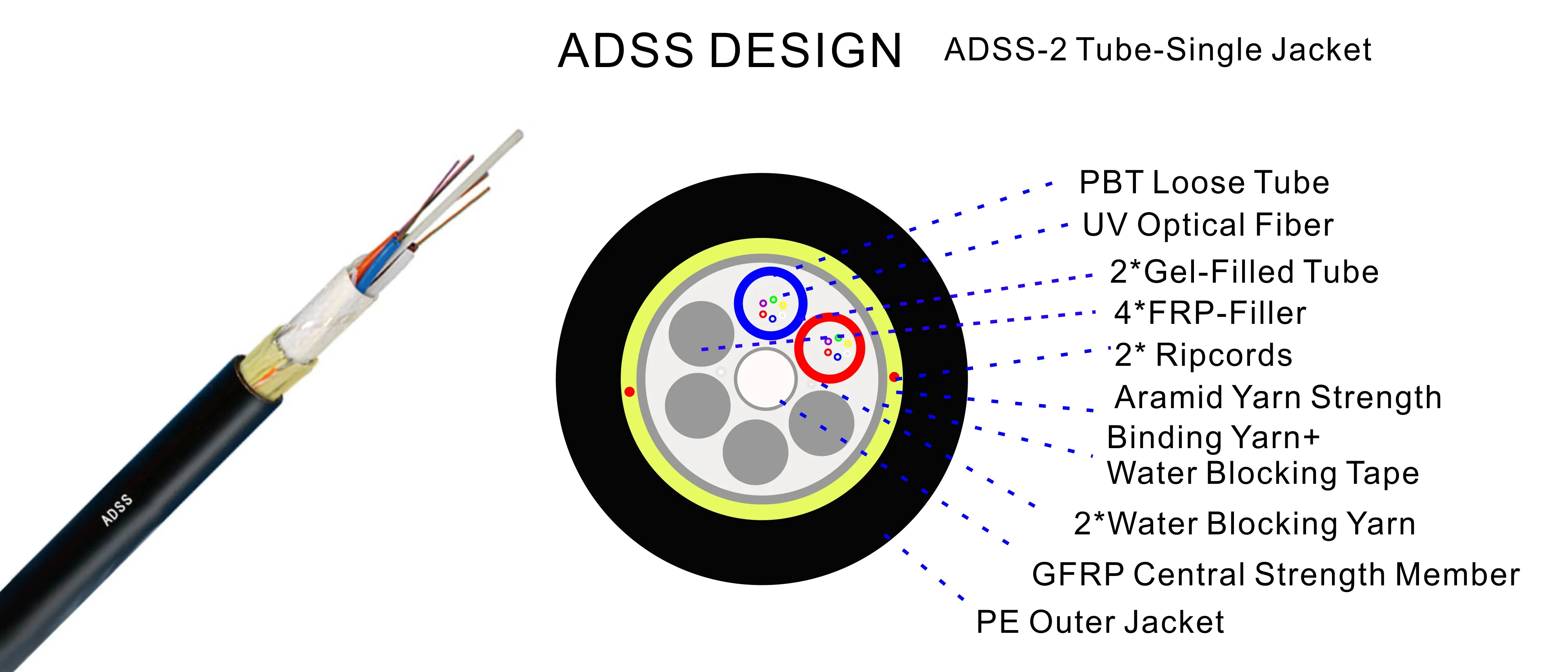
ADSS 12F 100M SPAN SM G652D Single Jacket Fiber Optical Cable
Max Span: 100m MAT=2700N
Max applied voltage: 110kv
Weather conditions: 25m/s wind speed + 0mm Ice Load
Item: Description
Fiber Optic: UV fiber G.652.D;@1310nm ≤0.35dB/km;
@1550nm ≤0.2dB/km;
Tube filling compound: Water Blocking & Moisture Proof Thyrotrophic gel
Loose tube: 1.8-2.0 mm PBT
Filler FRP: 1.8 mm LDPE / PP
Center strength member: 1.8 mm GFRP
Water blocking tape: 0.28mm thickness
Binder: 2 wires Polyester Yarns
Ripcords: 2 wires
Dielectric Strength Members: Aramid Yarns KEVLAR K49-3000D
Inner Jacket: 0.9-1.0mm thickness HDPE /MDPE
Outer Jacket: 1.6-2.0mm thickness HDPE /MDPE
Cable Out Diameter: 10.7±0.5mm
Cable Weight: 85±5kg
Length Cable/Spool: 3km or 4km (2% tolerance in more)
Temperature range: -20~+65℃
■ Standards:
ITU-T Rec. G.657A ISO9001
IEC 60794 ICEA-596
GR-409 YD/T 1997-2009
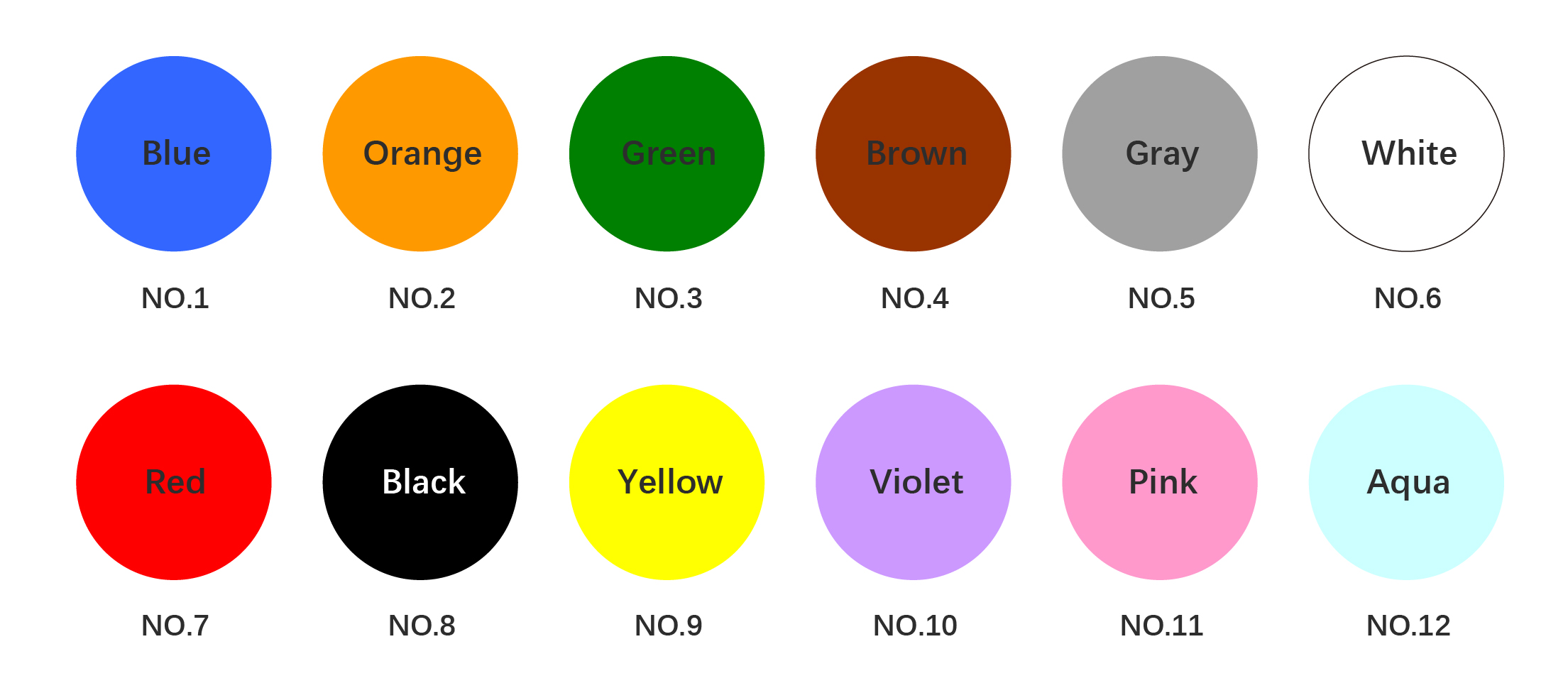
■ Colors -12 Chromatography:

■ Optical Characteristics:
Fiber Types:
1. G.652.D
2. G.655
3. 50/125μm Multimode
4. 62.5/125μm Multimode
Attenuation:
@850nm (Short wavelength)
o 50/125μm: ≤ 3.0 dB/km
o 62.5/125μm: ≤ 3.0 dB/km
@1300nm (Longer wavelength)
o 50/125μm: ≤ 1.0 dB/km
o 62.5/125μm: ≤ 1.0 dB/km
@1310nm (Standard transmission wavelength for single-mode)
o G.652.D: ≤ 0.36 dB/km
o G.655: ≤ 0.40 dB/km
@1550nm (Longest transmission wavelength, most efficient for long-distance transmission)
o G.652.D: ≤ 0.22 dB/km
o G.655: ≤ 0.23 dB/km
Bandwidth:
@850nm (High bandwidth for multimode)
o 50/125μm: ≥ 500 MHz·km
o 62.5/125μm: ≥ 200 MHz·km
@1300nm (Optimal for multimode fiber)
o 50/125μm: ≥ 1000 MHz·km
o 62.5/125μm: ≥ 600 MHz·km
Polarization Mode Dispersion (PMD):
· Individual fiber (Related to signal dispersion in fiber)
o G.652.D: ≤ 0.20 ps/√km
o G.655: ≤ 0.20 ps/√km
Design Link Value (M=20, Q=0.01%):
· G.652.D: ≤ 0.10 ps/√km
· G.655: ≤ 0.10 ps/√km
■ Technical Data:
Fiber Contents:
· Fiber Count Options:
o 6, 12, 24, 48, 72, 96, 144, 288 fibers
Loose Tube Configuration:
· Tubes per Fiber Count:
o 6 fibers: 1x6, 2x6, 4x6
o 8 fibers: 6x8
o 12 fibers: 4x12, 6x12, 8x12, 12x12
o 24 fibers: 24x12
Outer Diameter of Loose Tubes:
· Outer Diameter (mm):
o 1.8, 2.0, 2.5
o Adjustable (OEM): 1.5|2.0, 1.8|2.3, 2.1|2.3
Central Strength Member:
· Material: Glass Fiber Reinforced Plastic Rod (GFRP)
· Diameter (mm):
o Standard: 2.0, 2.5, 2.8, 3.7
o Adjustable (OEM): 1.8|2.3, 1.8|2.3, 2.5, 2.8, 3.7, 2.6
· PE Coated Diameter:
o No: Not PE coated for certain configurations
o Yes: PE coating on central strength member for specific designs
Water Blocking:
· Material: Water blocking tape for preventing water infiltration
Peripheral Strength Member:
· Material: Aramid Yarn for enhanced strength and protection
Outer Sheath:
· Thickness:
o Standard: 1.8mm (1.5-2.0mm for OEM)
· Cable Diameter (Approx.):
o 6 fibers: 9.5mm
o 12 fibers: 9.5mm|10mm
o 24 fibers: 12.2mm
o 48 fibers: 13.9mm
o 72 fibers: 17.1mm
o 96 fibers: 20.2mm
o Adjustable (OEM): 8.0|8.5|9.0|10.5|11.0mm
Operating Temperature Range:
· Range: -40°C to +70°C
Maximum Span:
· Span Options:
o 50m, 80m, 100m, 120m, 150m
Climate Conditions:
· No Ice: No ice formation is considered in design
· Maximum Wind Speed: 25m/s
MAT (Mechanical Test):
· Design Customization: Tailored according to customer-specific requirements
√ Other structure and fibre count are also available according to customer requirements.
√ Cable diameter and weight in this table is typical value, which will fluctuate according to different designs
√ The span needs to be recalculated due to other climate conditions according to the installation area.
Fiber Datas-SM
Fiber Optical Test Datas
The properties of single mode optical fiber (ITU-T Rec. G652|G657)
■ Transmission Characteristics:
·O Band (1260-1360 nm): Typically used in multimode optical fiber systems. The frequency range is 237.9-220.4 THz.
·E Band (1360-1460 nm): This range is less commonly used due to higher attenuation.
·S Band (1460-1530 nm): Frequently used in Passive Optical Networks (PON). The frequency range is 205.3-195.9 THz.
·C Band (1530-1565 nm): The most widely used range for long-haul fiber-optic transmission because it has minimum attenuation. The frequency range is 195.9-191.6 THz.
·L Band (1565-1625 nm): The second lowest attenuation range, used for extended reach and high-capacity networks. The frequency range is 191.6-184.5 THz.
·U Band (1625-1675 nm): Primarily used for network monitoring. The frequency range is 184.5-179.0 THz.
Attenuation Coefficient at Various Wavelengths:
·At 1310 nm, the attenuation is:
· G.652.D Normal: ≤0.35 dB/km
· G.652.D Best: ≤0.34 dB/km
· G.657.A1 & G.657.A2: ≤0.34 dB/km
·At 1285-1330 nm, the attenuation remains consistent for all fibers at:
· ≤0.37 dB/km
·At 1383 nm, the attenuation is slightly lower:
· G.652.D Normal & Best: ≤0.30 dB/km
· G.657.A1 & G.657.A2: ≤0.31 dB/km
·At 1490 nm, the attenuation is as follows:
· G.652.D Best: ≤0.23 dB/km
· G.657.A1 & G.657.A2: ≤0.23 dB/km
· G.652.D Normal: ≤0.24 dB/km
·At 1550 nm, which is the most commonly used wavelength for long-distance communication, the attenuation is:
· G.652.D Normal: ≤0.22 dB/km
· G.652.D Best: ≤0.21 dB/km
· G.657.A1 & G.657.A2: ≤0.20 dB/km
·At 1525-1575 nm, the attenuation is:
· G.652.D Normal: ≤0.22 dB/km
· G.652.D Best: ≤0.21 dB/km
· G.657.A1 & G.657.A2: ≤0.21 dB/km
·At 1625 nm, the attenuation is slightly higher for all fibers:
· G.652.D Normal: ≤0.25 dB/km
· G.652.D Best: ≤0.24 dB/km
· G.657.A1 & G.657.A2: ≤0.22 dB/km
The Mode Field Diameter (MFD) is a crucial parameter that determines the effective size of the core through
which light propagates in an optical fiber. It affects the fiber's coupling efficiency with light sources, especially
for splicing or connecting to other fiber optic components. Here's the MFD for different fiber types at key wavelengths:
At 1310 nm, the Mode Field Diameter is:
o G.652.D Normal: 8.6 ± 0.4 µm
o G.652.D Best: 9.0 ± 0.4 µm
o G.657.A1: 9.0 ± 0.3 µm
o G.657.A2: 8.6 ± 0.4 µm
At 1550 nm, the Mode Field Diameter is:
o G.652.D Normal: 9.8 ± 0.5 µm
o G.652.D Best: 10.2 ± 0.4 µm
o G.657.A1: 10.2 ± 0.4 µm
o G.657.A2: 9.6 ± 0.5 µm
Zero Dispersion Wavelength & Dispersion Coefficient
The zero dispersion wavelength refers to the point at which the fiber exhibits no dispersion (i.e., the spreading of light pulses over distance).
The dispersion coefficient characterizes how much the fiber disperses light pulses, which affects signal integrity over long distances.
· Zero Dispersion Wavelength: 1300-1324 nm for all variants.
· Dispersion Coefficient at 1285-1339 nm:
o G.652.D: ≤3.4 ps/(nm·km)
o G.657.A1 & A2: ≤3.4 ps/(nm·km)
Polarization Mode Dispersion (PMD)
· PMD Maximum Individual Fiber: ≤0.1 ps/√km for all fiber types.
· PMD Link Design Value: ≤0.06 ps/√km.
Key Findings at Different Wavelengths:
At 1550 nm:
o When the fiber is bent with a 15mm radius (10 turns), the loss is very small, ≤0.25 dB.
o 100 turns of a 25mm radius result in a minimal loss of ≤0.03 dB.
o A 10mm radius bend (1 turn) causes a larger loss, ≤0.75 dB.
o A 7.5mm radius bend (1 turn) results in a moderate loss of ≤0.2 dB.
o 100 turns with a 30mm radius causes very low loss, ≤0.05 dB.
At 1625 nm:
o Bending loss increases more noticeably, with 10 turns of a 15mm radius causing ≤1.0 dB of loss.
o A 10mm radius bend (1 turn) results in higher loss, ≤1.5 dB.
o 1 turn of a 7.5mm radius leads to ≤0.5 dB of loss.
Point Discontinuity
Point discontinuities are imperfections or abrupt changes in fiber properties that cause attenuation. These values are critical to ensure minimal signal degradation.
· Point Discontinuity at 1310 nm & 1550 nm: ≤0.05 dB for all fibers.
■ Dimensions:
·Cladding Diameter:
· G.652.D Normal: 125 ± 0.7 µm
· G.652.D Best: 125 ± 0.5 µm
· G.657.A1: 125 ± 0.5 µm
· G.657.A2: 125 ± 0.5 µm
· Unit: Micrometers (µm)
The cladding diameter refers to the outer layer of the fiber that surrounds the core. It is crucial for ensuring proper fiber alignment during installation and performance.
·Core/Cladding Concentricity Error:
· G.652.D Normal: ≤ 0.5 µm
· G.652.D Best: ≤ 0.4 µm
· G.657.A1: ≤ 0.4 µm
· G.657.A2: ≤ 0.4 µm
· Unit: Micrometers (µm)
This refers to the precision of the core's alignment within the cladding. A smaller concentricity error ensures better light transmission and performance.
·Cladding Non-circularity:
· G.652.D Normal: ≤ 1.0%
· G.652.D Best: ≤ 0.7%
· G.657.A1: ≤ 0.7%
· G.657.A2: ≤ 0.7%
· Unit: Percentage (%)
This measures how much the cladding deviates from being a perfect circle. A lower value indicates better consistency in the fiber’s shape, which is essential for reducing signal loss and ensuring efficient transmission.
·Coating Diameter:
· G.652.D Normal: 245 ± 5 µm
· G.652.D Best: 245 ± 5 µm
· G.657.A1: 242 ± 5 µm
· G.657.A2: 242 ± 5 µm
· Unit: Micrometers (µm)
The coating is a protective layer that surrounds the fiber to prevent physical damage. The coating diameter is crucial for the handling and strength of the fiber.
·Coating/Cladding Concentricity Error:
· G.652.D Normal: ≤ 12 µm
· G.652.D Best: ≤ 12 µm
· G.657.A1: ≤ 8 µm
· G.657.A2: ≤ 8 µm
· Unit: Micrometers (µm)
■ Mechanical Characteristics:
·Fiber Strain:
· Requirement: ≥ 1%
· This represents the amount of strain the fiber can withstand before failure. It ensures the fiber maintains its integrity under stress and stretching during handling and installation.
·Fiber Load:
· Requirement: ≥ 9 N (Newtons)
· The fiber load specifies the force required to stretch the fiber before it fails. It is essential for ensuring that the fiber can handle mechanical stress during use.
·Stress:
· Requirement: ≥ 100 kpsi (kilo pounds per square inch)
· This measures the stress the fiber can withstand before breaking. A higher value indicates better resistance to mechanical forces that could cause the fiber to break.
·Dynamic Stress Corrosion Susceptibility Factor:
· Unaged & Aged (30 days @ 85°C, 85% R.H.): ≥ 20
· This factor indicates the fiber's resistance to stress corrosion under dynamic conditions. A higher value means the fiber is more resistant to corrosion and can maintain performance even in harsh environments.
·Coating Strip Force (Peak Value):
· Range: 1.3 - 8.9 N
· The coating strip force measures the amount of force required to strip off the protective coating without damaging the fiber. This ensures proper handling during installation and maintenance.
·Fiber Curl:
· Requirement: ≥ 4 m
· Fiber curl refers to the natural tendency of the fiber to curl up when uncoiled. This specification ensures the fiber remains stable and can be properly installed without unwanted coiling or tangling.
■ Environmental Characteristics:
·Dry Heat Aging (30 days @ 85°C):
· Attenuation @1310 nm: ≤0.05 dB/km
· Attenuation @1550 nm: ≤0.05 dB/km
· Description: This test measures the fiber's ability to maintain its performance when exposed to dry heat over an extended period. The low attenuation indicates minimal degradation in the fiber's signal transmission properties after 30 days of exposure to high temperature (85°C).
·Accelerated Aging (30 days @ 85°C, 85% Relative Humidity):
· Attenuation @1310 nm: ≤0.05 dB/km
· Attenuation @1550 nm: ≤0.05 dB/km
· Description: This test simulates long-term exposure to both heat and high humidity. It helps determine how well the fiber performs under aging conditions. The low attenuation values show that the fiber remains stable even in harsh environmental conditions.
·Temperature Cycling:
· Attenuation @1310 nm: ≤0.05 dB/km
· Attenuation @1550 nm: ≤0.05 dB/km
· Description: Temperature cycling tests the fiber's ability to withstand temperature fluctuations without significant performance degradation. The fiber must maintain low attenuation during these cycles to ensure reliable performance in environments with variable temperatures.
·Water Soak (30 days @ 23°C):
· Attenuation @1310 nm: ≤0.05 dB/km
· Attenuation @1550 nm: ≤0.05 dB/km
· Description: This test exposes the fiber to water to simulate conditions where the fiber may encounter moisture or water over time. The low attenuation values suggest that the fiber is well-protected against water-related degradation and performs reliably even in wet conditions.
■ Main TEST for Mechanical & Environmental Characteristics:
1. Tensile Strength (IEC 794-1-E1)
· Test Method:
o Apply a load of 5000 N over a 50m cable length.
· Acceptance Requirements:
o The loss change should not exceed 0.1 dB at 1550 nm.
o No fiber break and no sheath damage should occur.
2. Crush Test (IEC 60794-1-E3)
· Test Method:
o Apply a load of 3000 N over 100 mm of cable for ≥1 minute.
· Acceptance Requirements:
o The loss change should not exceed 0.1 dB at 1550 nm.
o No fiber break and no sheath damage should occur.
3. Impact Test (IEC 60794-1-E4)
· Test Method:
o Apply 5 points of impact, 5 times per point.
o Impact energy: 4.5 Nm.
o Radius of hammerhead: 12.5 mm.
o Impact rate: 2 seconds per cycle.
· Acceptance Requirements:
o The loss change should not exceed 0.1 dB at 1550 nm.
o No fiber break and no sheath damage should occur.
4. Repeated Bending (IEC 60794-1-E6)
· Test Method:
o Bend the cable with a bending diameter of 20x its outer diameter (OD).
o Apply a load of 250 N with a flexing rate of 3 seconds per cycle for 30 cycles.
· Acceptance Requirements:
o The loss change should not exceed 0.1 dB at 1550 nm.
o No fiber break and no sheath damage should occur.
5. Torsion (IEC 60794-1-E7)
· Test Method:
o Length: 1 meter.
o Apply a load of 150 N with a twist rate of 1 minute per cycle.
o Twist angle: ±90°.
o Number of cycles: 10.
· Acceptance Requirements:
o The loss change should not exceed 0.1 dB at 1550 nm.
o No fiber break and no sheath damage should occur.
6. Water Penetration (IEC 60794-1-F5B)
· Test Method:
o Submerge the cable in 1 meter of water for 24 hours.
o Sample length: 3 meters.
· Acceptance Requirements:
o No water leakage from the opposite end of the cable.
7. Temperature Cycling (IEC 60794-1-F1)
· Test Method:
o Temperature steps: +20°C → -20°C → +20°C → +40°C.
o Time per step: 24 hours.
o Number of cycles: 2.
· Acceptance Requirements:
o The loss change should not exceed 0.1 dB at 1550 nm.
o No fiber break and no sheath damage should occur.
8. Compound Flow (IEC 60794-1-E14)
· Test Method:
o Sample length: 30 cm.
o Temperature: 70°C ± 2°C.
o Duration: 24 hours.
· Acceptance Requirements:
o No compound flow should occur.
9. Sheath High Voltage Test
· Test Method:
o Perform an online test with a 9 kV voltage (dependent on sheath thickness).
· Acceptance Requirements:
o No sheath breakdown should occur.
■ Cable Marking&Fibers Colors:
Sheath marking
COMPANY Fiber cable name N*cores G.652D 2024 XXXXm
COMPANY:Manufacturer's brand
2024:Manufacture year
Fiber cable name:Cable type
G.652D:N cores single-mode optical fiber (ITU-T Rec. G.652D)
XXXXm:Mark of meters
*The marking is printed every 1 meter;
**”G.652D” means ITU-T Rec. Low Water Peak (LWP) G.652 single mode optical fiber..
Also can according to client cable marking.
1 The color of marking is white,
2 An occasional unclear of length marking is permitted if both of the neighboring markings are clear.
3 The both cable ends are sealed with heat shrinkable end caps to prevent water ingress.
■ Fiber color and Binder color code: according to EIA/TIA 598B:
Display prices in:XOF